How to reverse a dc motor?
DC motors are widely used in industrial production. Changing the rotation direction of the DC motor can make the machine more powerful.
The humble DC motor, a workhorse of the industrial and engineering world, has powered countless machines and devices for over a century. But what happens when you need it to change direction? Reversing a DC motor's rotation, while seemingly straightforward, involves nuanced principles and practical considerations. This essay delves into the technological intricacies of reversing DC motors, exploring various methods, potential pitfalls, and practical applications.
The Physics of DC Motor Rotation
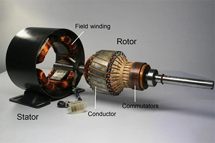
Before diving into reversal techniques, let's establish the underlying principles governing DC motor operation. A DC motor's core components are the stator (containing field magnets) and the rotor (an electromagnet with windings). Applying a voltage to the rotor windings creates a magnetic field that interacts with the stator's field, generating torque and causing the rotor to spin.
The direction of rotation depends on the alignment of these magnetic fields. When the polarities of the rotor and stator fields match, they attract and repel, creating a torque that propels the rotor in one direction. Conversely, opposing polarities cause the fields to repel each other, resulting in rotation in the opposite direction. This fundamental principle of magnetic interaction forms the basis for all DC motor reversal methods.
Swapping the Supply Leads - A Simple Yet Effective Approach
The most basic and common method for reversing a DC motor involves simply swapping the polarity of the voltage applied to its terminals. Imagine a DC motor connected to a battery with red (+) and black (-) terminals. When the red lead connects to the motor's positive terminal and the black lead to the negative terminal, the motor spins in a specific direction (let's say clockwise for this example).
To reverse the rotation, we simply swap the leads. Now, the red lead connects to the negative terminal, and the black lead to the positive terminal. This effectively reverses the polarity of the voltage applied to the rotor windings, causing the magnetic fields to oppose each other and drive the rotor in the opposite direction (counterclockwise in this case).
This method's simplicity and ease of implementation make it ideal for basic applications like toy cars or simple robotics projects. However, it's crucial to remember that swapping leads directly can generate sparks and potentially damage the motor due to sudden current spikes. Additionally, this method provides limited control over the reversed rotation speed and torque.
H-Bridge Circuits - Precise Control and Bidirectional Operation
For more demanding applications requiring precise control over the reversed rotation, H-bridge circuits come into play. These electronic circuits employ four switches arranged in an "H" formation, allowing independent control of current flow to the motor's windings. By strategically turning the switches on and off in specific sequences, the H-bridge circuit can not only reverse the motor's direction but also control its speed and braking.
The advantages of H-bridge circuits are numerous. They enable smooth and controlled bi-directional operation, protecting the motor from sudden current surges. Additionally, many H-bridge circuits offer features like pulse-width modulation (PWM) for fine-tuning motor speed and current limiting for overload protection.
However, H-bridge circuits are generally more complex to implement than simple lead swapping. They require careful component selection, circuit design, and potentially programming depending on the chosen controller.
Field Winding Reversal and Electronic Commutation
Beyond the basic methods, more advanced techniques exist for specific applications:- Field Winding Reversal: In some DC Motors, the magnetic field of the stator (instead of the rotor) can be reversed. This involves physically changing the connections of the field windings, a technique typically employed in large industrial motors where direct rotor lead access is impractical.
- Electronic Commutation: Brushless DC (BLDC) motors utilize electronic commutation to control the rotation. By electronically switching the current to the motor windings at specific intervals, BLDC motors achieve smooth and efficient bi-directional operation without the need for physical brushes or commutators.
These advanced methods offer greater control and efficiency but require specialized knowledge and equipment, making them less suitable for general DIY projects.


Leave a Comment